

simpleEMS#



simpleEMS is a python library built on top of openEMS to make the design of antennas and other RF structures simpler.
Motivation#
This Python package provides an alternative to proprietary suites with expensive licenses or the restrictive “Student” versions such as CST, HFSS and Sonnet which often impose stifling mesh cell limits and memory caps. By leveraging the openEMS FDTD engine, it offers a scalable framework for simulating, optimizing, and visualizing complex RF designs. whether you are a professional engineer, a freelancer, or a dedicated hobbyist, this library will enable you to design RF circuits easily.
Key Features:#
Antenna Design#
Inset-Fed Patch Antenna Design
Probe-Fed Patch Antenna Design
Filter Design#
Bandpass Quarter-Wave Filter Design
Bandstop Quarter-wave Filter Design
Simulation & Optimization#
Parameter Sweep
S11 Optimization
S21 Optimization
Network Parameters Calculation#
S11 (Reflection Coefficient)
S21 (Insertion Loss)
VSWR (Voltage Standing Wave Ratio)
Z11 (Input Impedance)
Input Power
Visualization & Plotting#
Geometry Structure Visualization
S11 Plotting
S21 Plotting
VSWR Plotting
Smith Chart for S11
Complex Impedance (Z11) Plotting
2D Radiation Pattern
2D Directivity Plot
3D Radiation Pattern, Gain & Power Plot
Field Dump#
Field Dump for ParaView
E-Field (Time and Frequency Domain)
H-Field (Time and Frequency Domain)
Current Density (Time and Frequency Domain)
Export Options#
Gerber Export
STEP Export
STL Export
Touchstone SnP Export
Solver Backends#
simpleEMS supports two solver backends, selected via backend_engine on your sim params:
FDTD (default) — powered by openEMS, the original time-domain backend.
FEM (experimental) — a frequency-domain finite-element backend (via GetDP) available since v0.2.0, for cases where FDTD isn’t the right fit. It shares the same plotting, sweep, optimization, and export APIs as the FDTD path, and can also mesh a raw STEP file directly without building a CSXCAD geometry first. API and behavior may still change.
See the FEM installation guide and the standalone FEM STEP tutorial in the docs.
Demo#
This example creates an inset fed patch antenna and simulates the created model.
#!/usr/bin/env python3
"""Simple inset-fed patch antenna example at 2.45 GHz."""

# IMPORTS
from simpleEMS import (
    InsetFedPatchAntenna,
    InsetFedPatchParams,
    setup_simulation,
)

# IMPORTS

# PARAMS
params = InsetFedPatchParams(
    resonant_freq=2.45e9,
    span_freq=0.5e9,
    substrate_thickness_mm=1.6,
    substrate_eps_r=4.4,
    substrate_tand=0.001,
    charac_imp=50,
)
# PARAMS

# SETUP
sim = setup_simulation(params)
# SETUP

# BUILD
patch = InsetFedPatchAntenna(params, sim)
patch.print_and_save_params(params)
port = patch.build_inset_fed_patch_antenna()
patch.create_mesh()
nf2ff = patch.create_nf2ff(sim)
patch.add_field_dump(sim, params)
patch.write_and_show_structure(sim)
# BUILD

# SIMULATE
patch.run_simulation(sim)
# SIMULATE

# PPROCESS
sim_data = patch.compute_sim_data(sim, port)
nf2ff_3d_result = patch.compute_nf2ff_3d(nf2ff, params.resonant_freq)
patch.plot_s_param(sim_data.freqs, sim_data.s11)
patch.plot_smith_chart(sim_data.freqs, sim_data.s11)
patch.plot_vswr(sim_data.freqs, sim_data.vswr)
patch.plot_impedance(sim_data.freqs, sim_data.z11)
patch.plot_2d_directivity(nf2ff, params.resonant_freq)
patch.plot_2d_rad_pattern(nf2ff, params.resonant_freq)
patch.plot_3d_directivity(nf2ff_3d_result, params.resonant_freq)
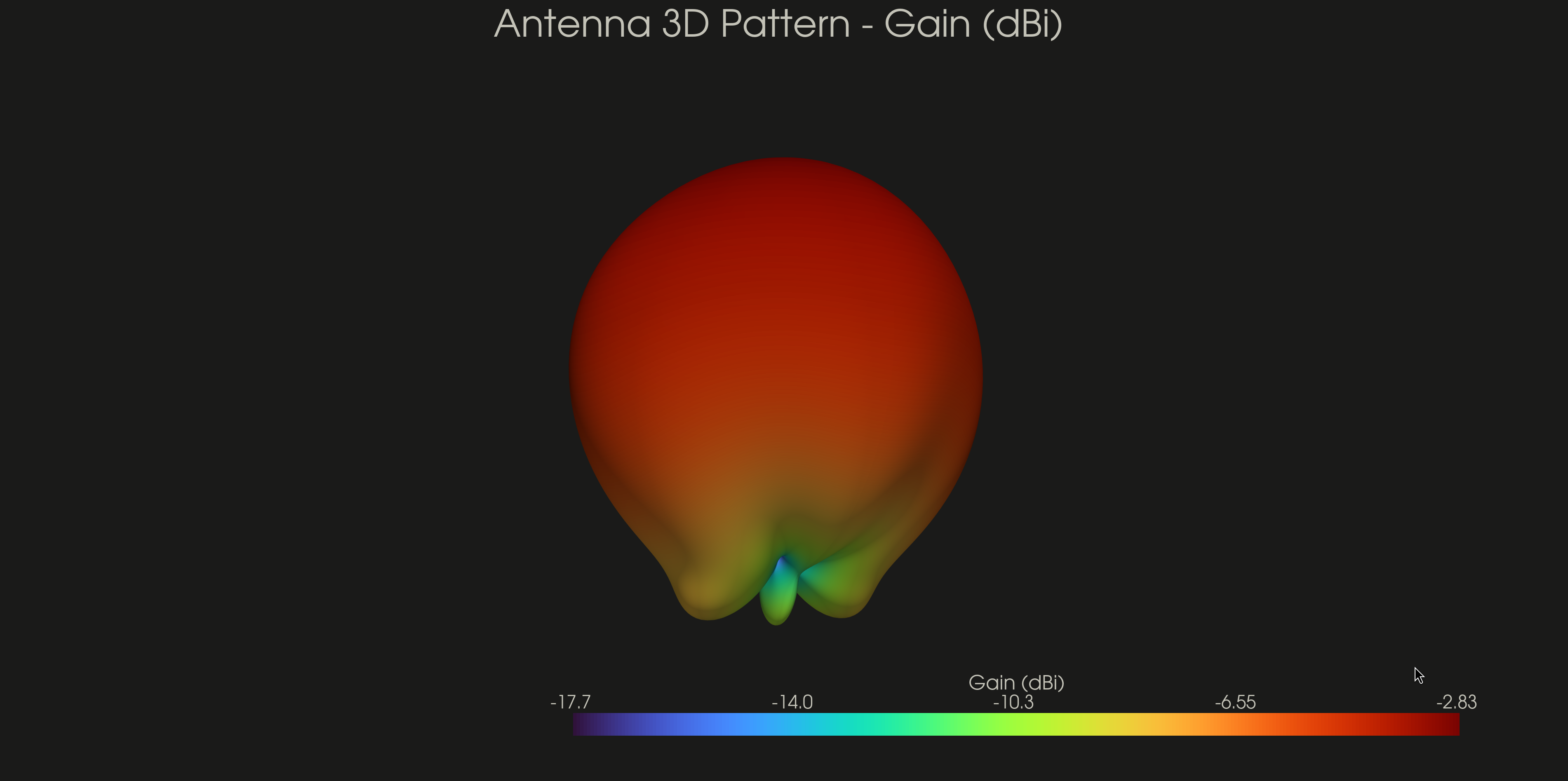
patch.plot_3d_gain(nf2ff_3d_result, params.resonant_freq, sim_data.input_power)
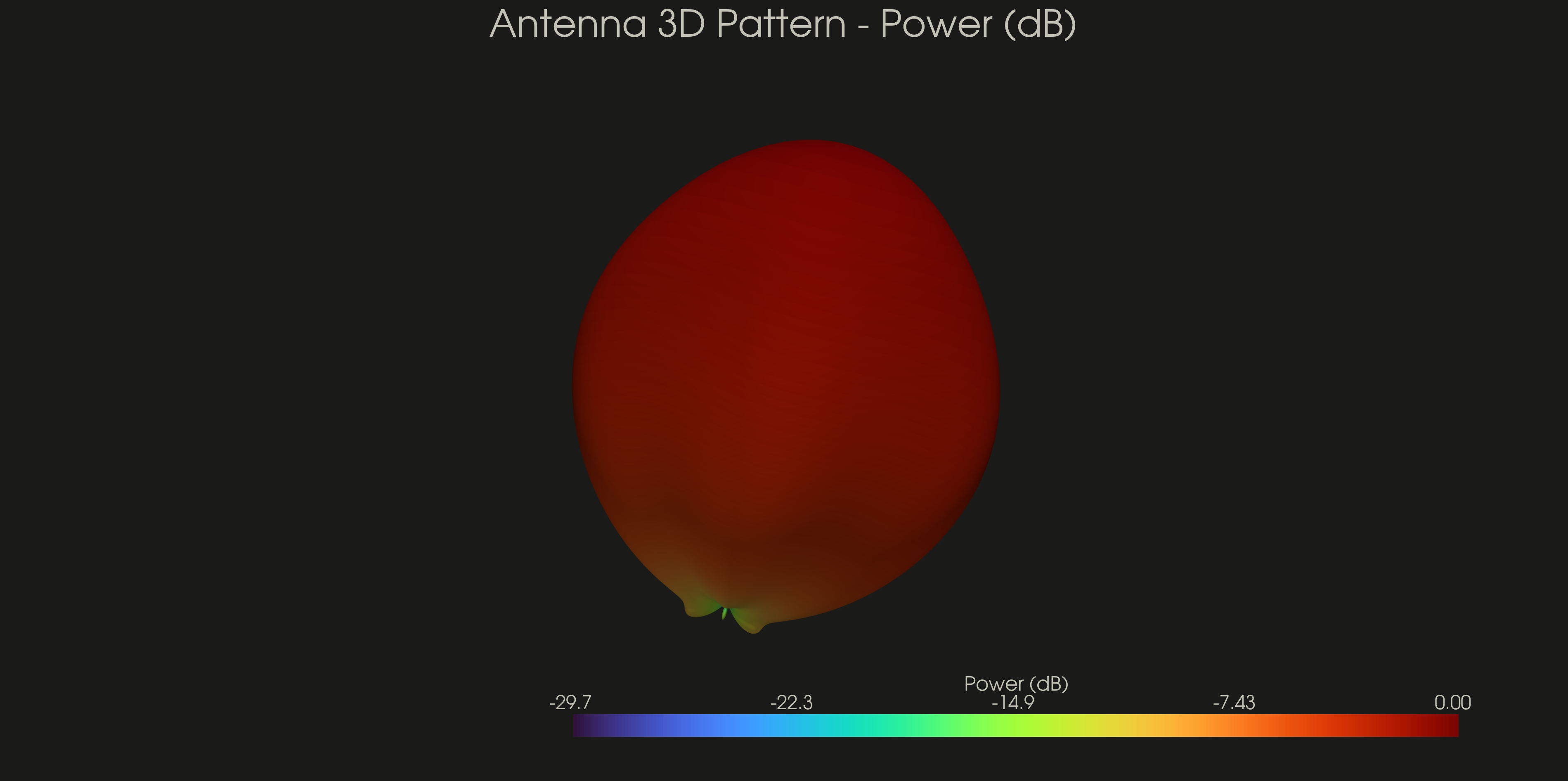
patch.plot_3d_power(nf2ff_3d_result, params.resonant_freq)
patch.save_plots()
patch.show_plots()
# PPROCESS

# EXPORT
patch.export_stl(sim)
patch.export_touchstone(
    sim_data.freqs,
    sim_data.s11,
    charac_imp=params.charac_imp,
)
patch.export_gerber(sim)
# EXPORT
Below is a visualisation of the model created by the above code
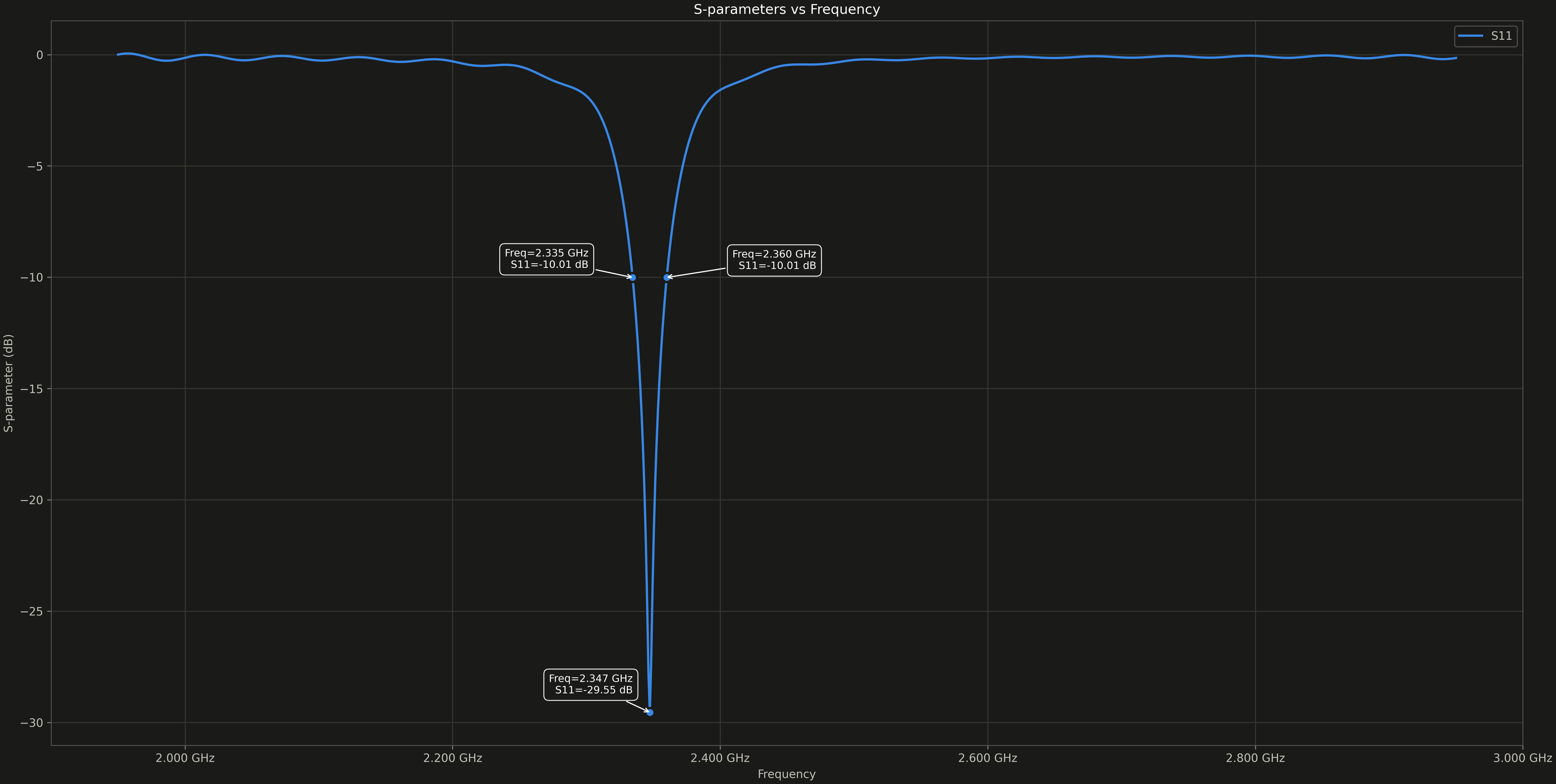
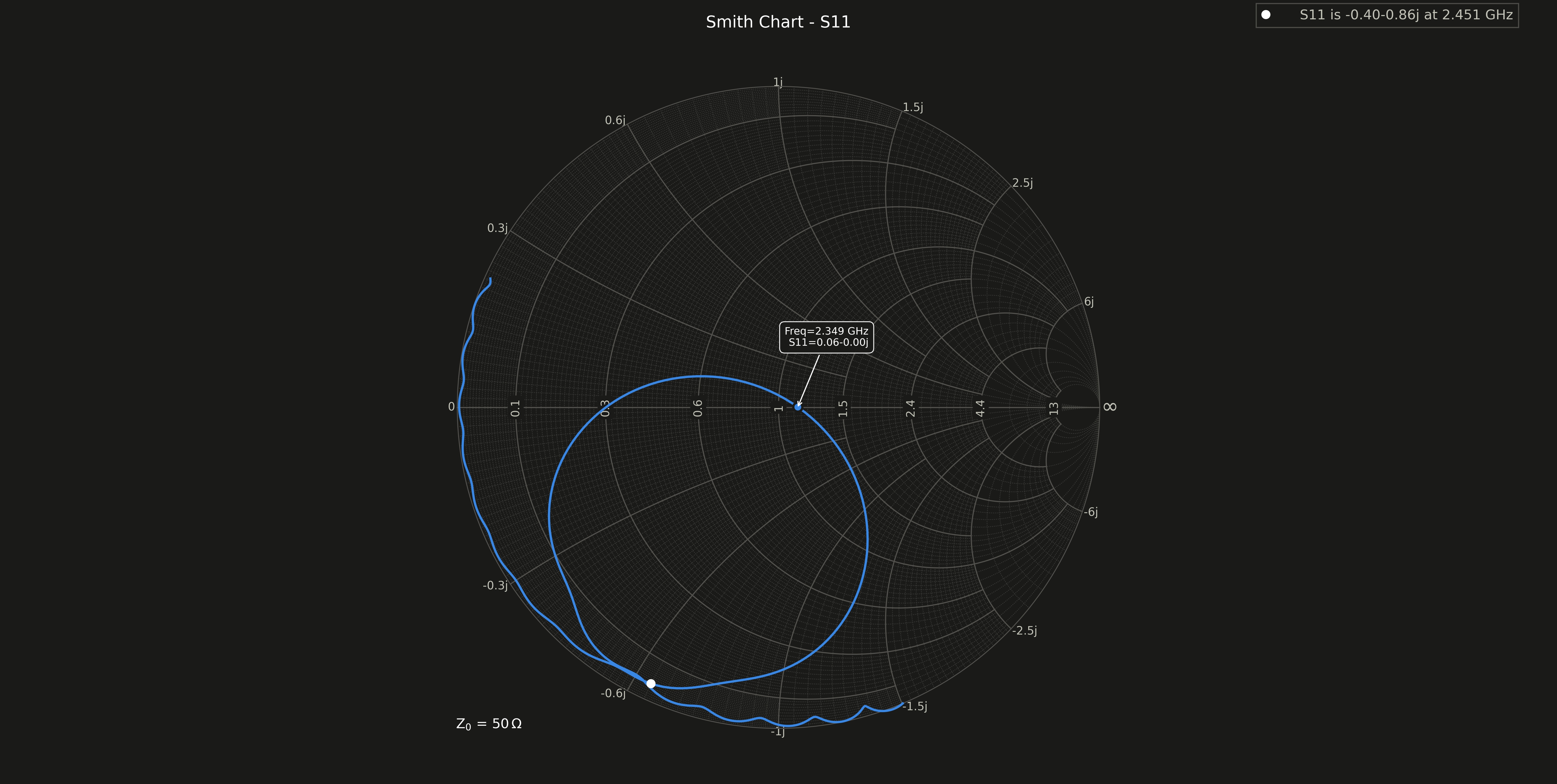
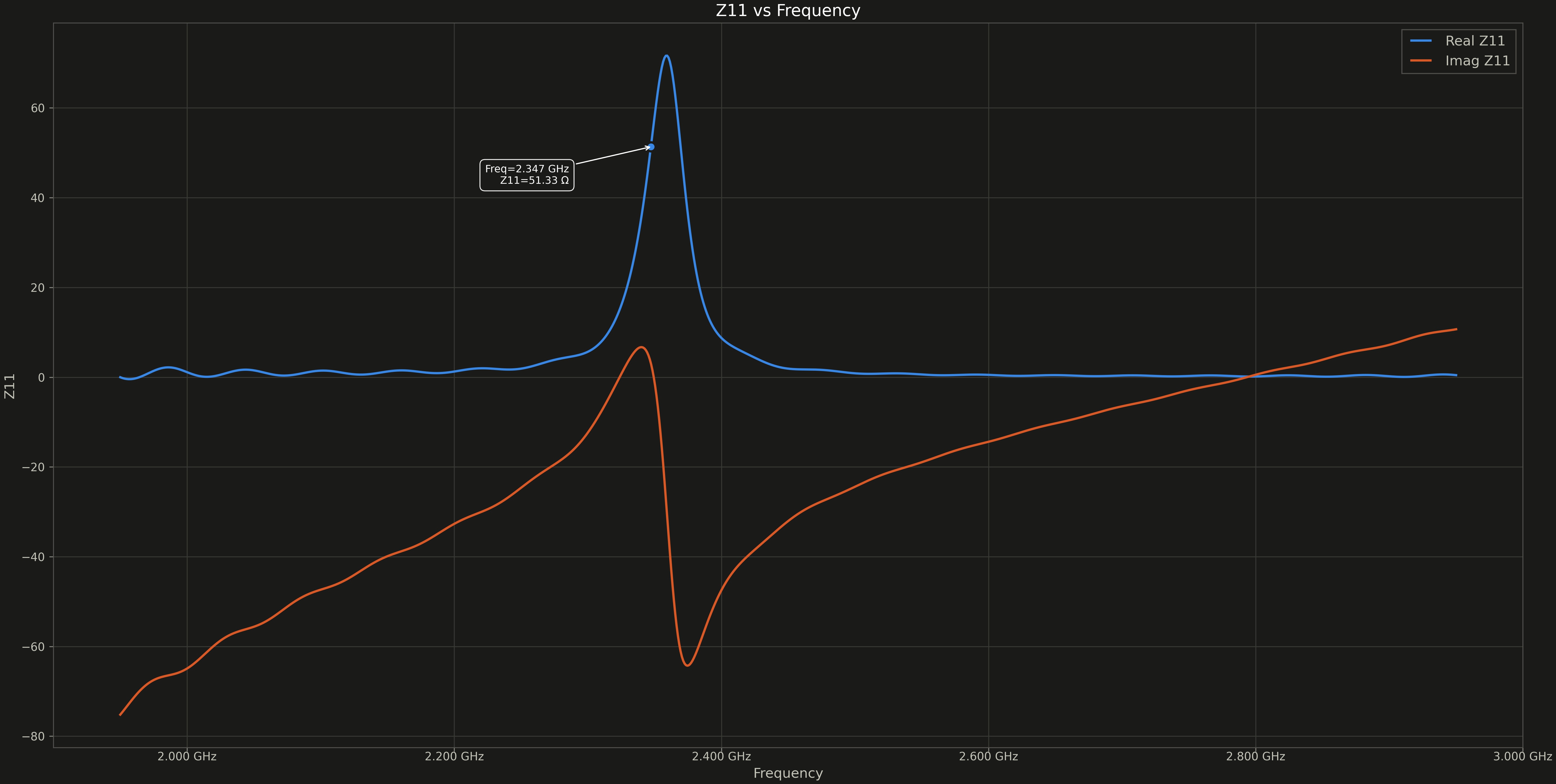
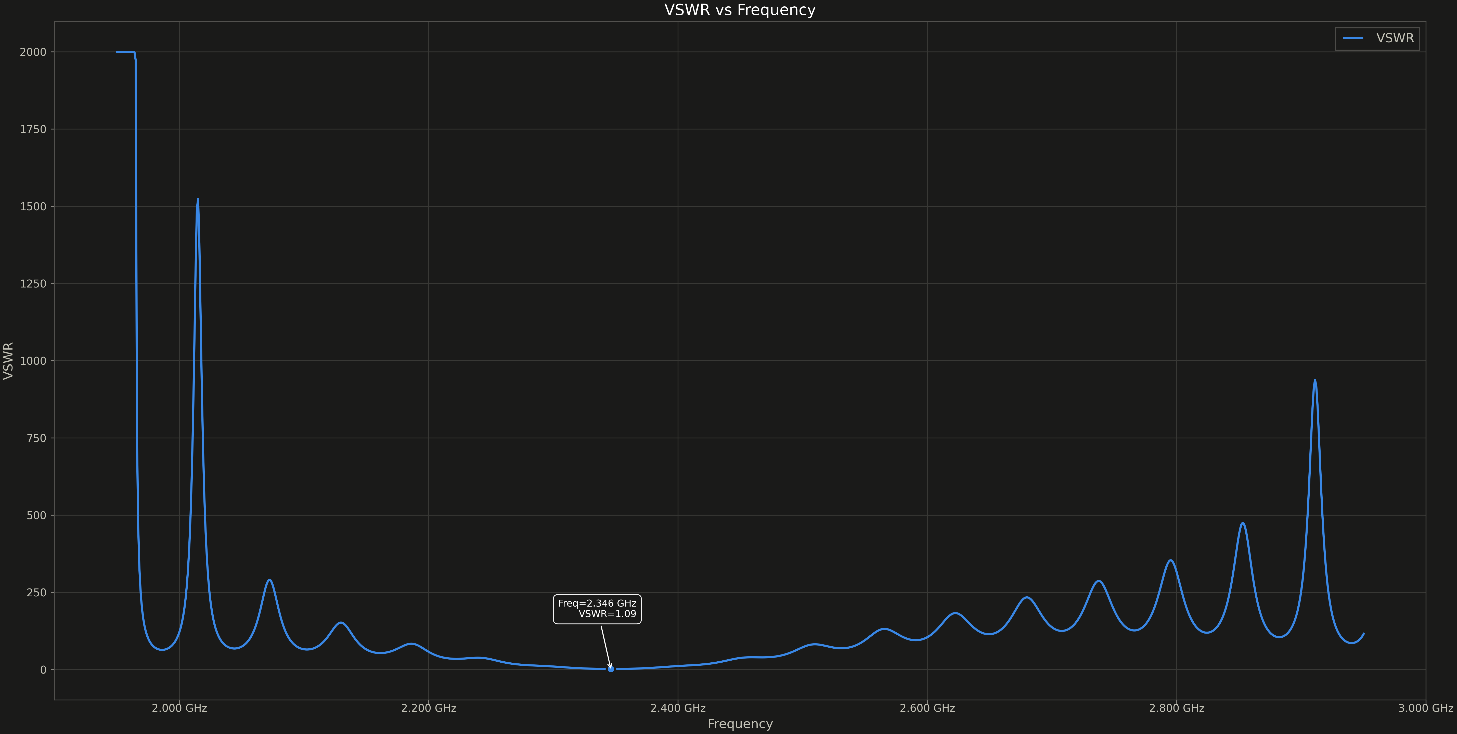
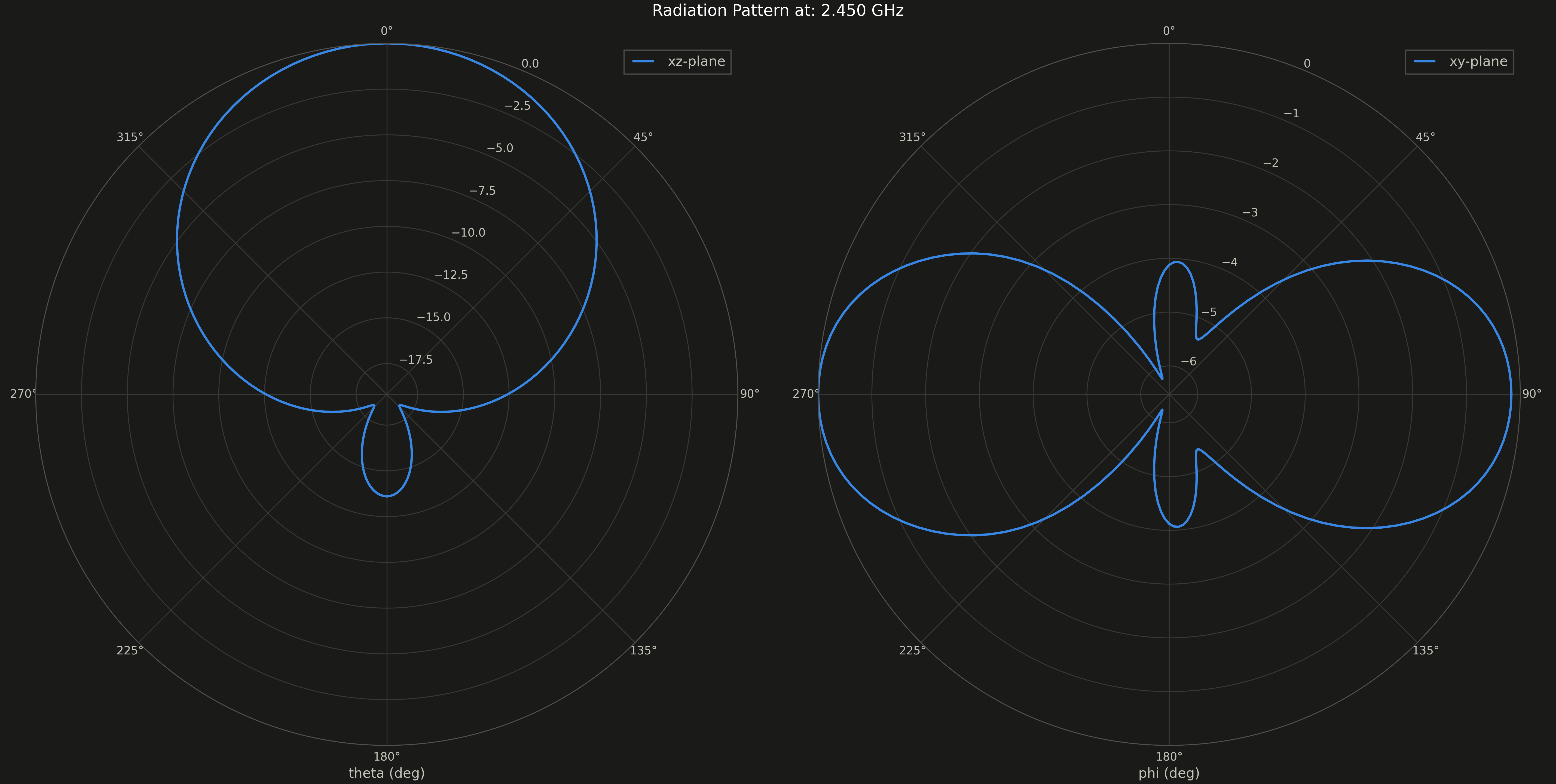
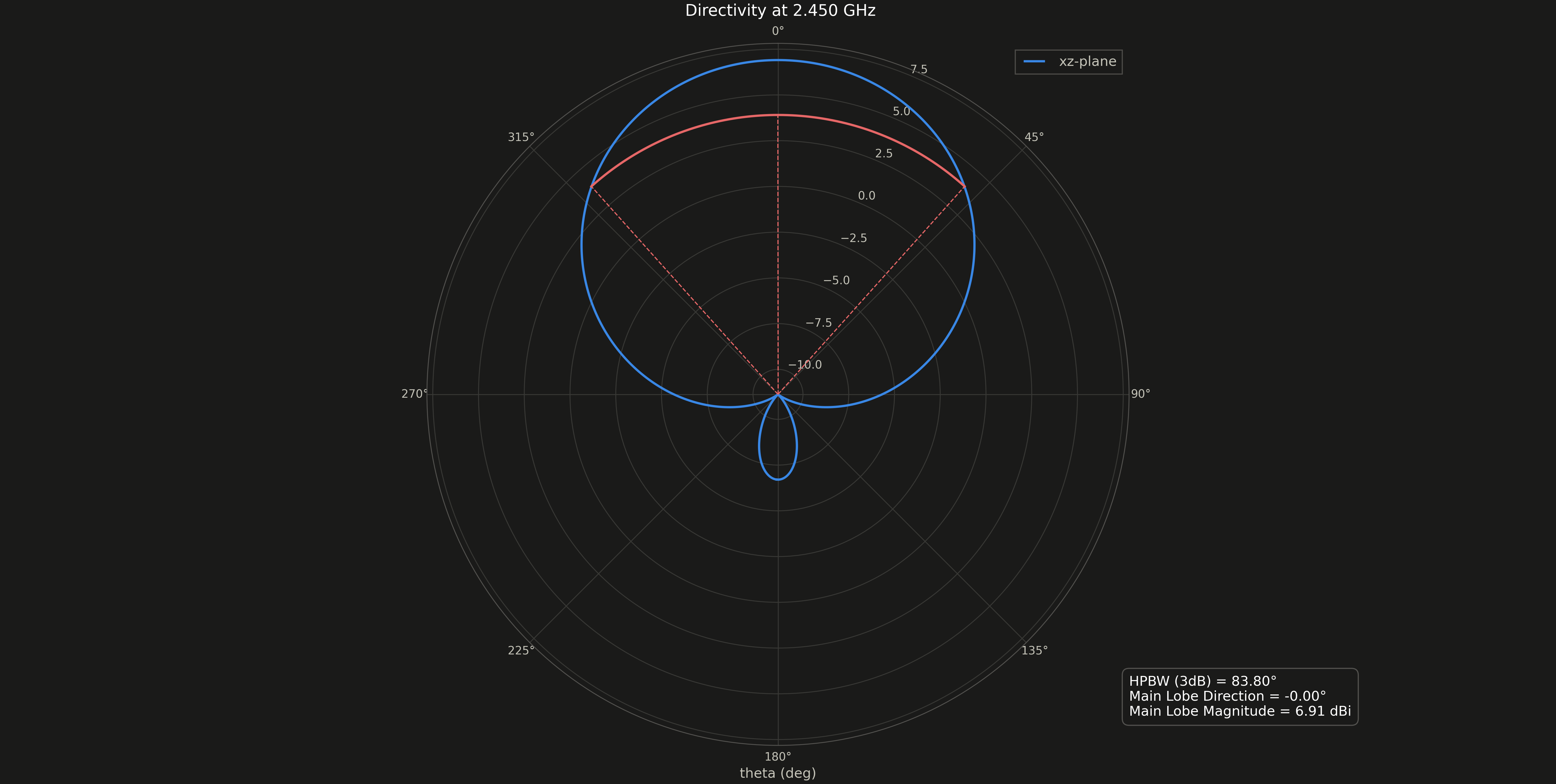
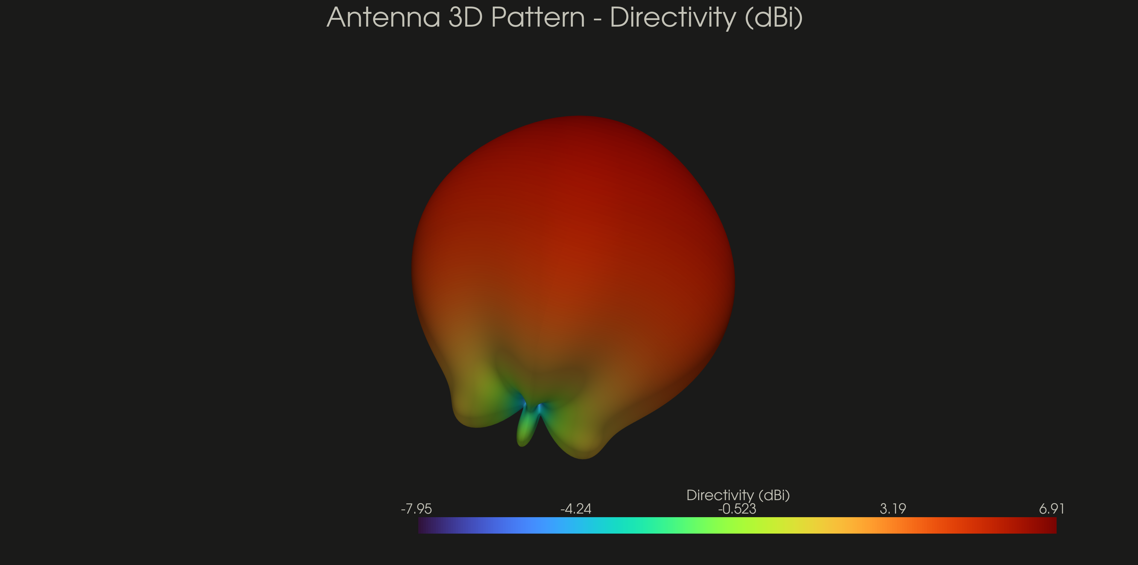
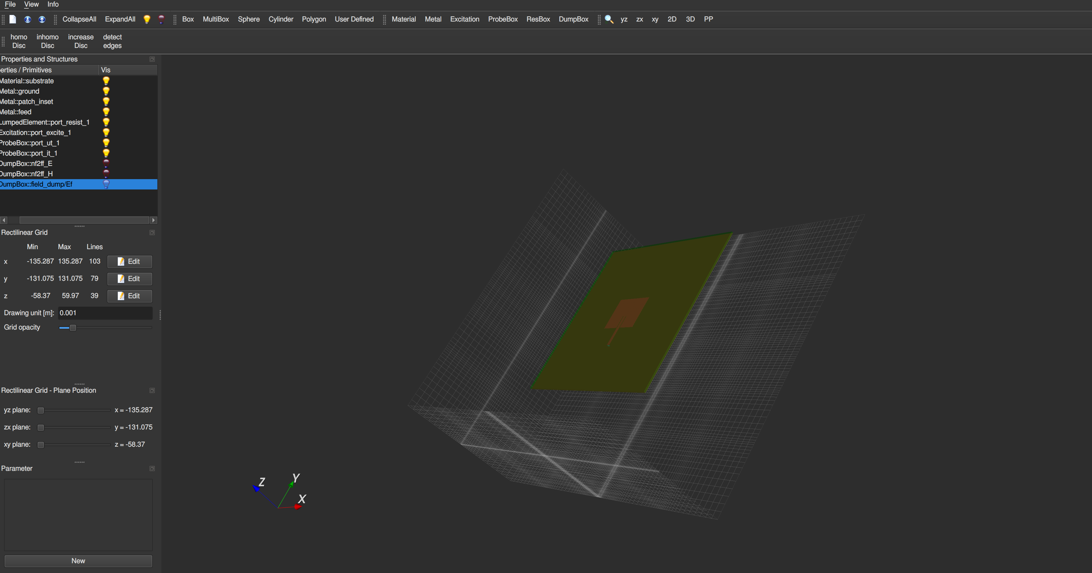 The result of the simulation
Installation#
Refer to the installation instructions in the docs.